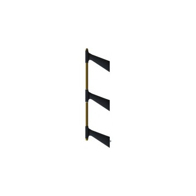
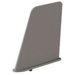
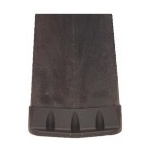
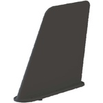
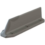
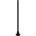
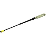
These antennas comprise an aluminium alloy tubular element of 1 inch diameter spaced off from the aircraft fuselage by three or more raked back, aerodynamic supporting masts. They can be installed in grounded (“loop”) or ungrounded configurations and are for use on helicopters and sub-sonic fixed wing aircraft.
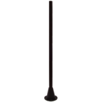
Support masts are available in 10 inch (to centre of tube) height and can have clamping or sliding head caps. Also available are switched grounding masts to enable the HF antenna to be switched between grounded loop and open-ended radiator.
In addition, a number of different feed-in mast types are available having either coaxial (HN) or single terminal connectors and clamping masts are available as insulators or conductors for use where grounding of the element is required. In the case of clamping masts, connection to the tube is made via an extremely secure, twin set screw arrangement that also provides a highly reliable RF connection. It is possible to connect 2 or more tubular elements by use of a 21-10-125 clamping joints or by joining them within the clamping mast head cap. The clamping arrangement allows for rapid assembly and disassembly of the array.
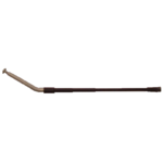
Element tubes, which are fitted with metal end plugs, are available in lengths from 4 feet to 15 feet and can also be custom bent for specific applications.
| Description | 10 inch stand-off |
| Feed in mast HN connector | 21-10-110 |
| Feed in mast long series HN connector | 21-10-111 |
| Feed in mast 10:32 stud | 21-10-112 |
| Support mast sliding head | 21-10-100 |
| Support mast clamping head insulated | 21-10-120 |
| Support mast clamping head, grounded | 21-10-121 |
| Element tubes | Can be straight or bent, dependant upon installation Requirements - request advice from Cooper Antennas Ltd |
| 21-10-100 | |
| Model # | 21-10-100 |
| Brand | Cooper Antennas |
21-10-100 series antenna arrays are capacitive and/or inductive tubular radiating elements that offer low resistive losses together with low capacitive feed through and support masts.
| Frequency | Typically 2-30 MHz (dependent upon associated coupler) |
| RF Voltage Rating (max) for typical support mast: | 5 kV Peak at 2 MHz |
| Mast Insulation: | ≥ 40 MΩ at 1000 V dc |
| Resistance through Conducting Paths: | ≤ 2.5 mΩ for lead in mast, grounded masts and across captive head couplers. |
| Radiation Diagram and Polarization: | Dependent upon configuration and airframe. |
Finish
- Urethane Lusterless Black


