Digital Logic Converter Unit
SKU: 21-131-700
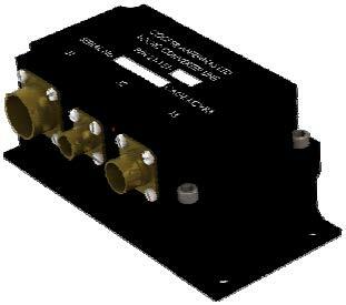
Military aircraft need to be able to depend on and maintain communications for broadband, frequency hopping V/UHF secure communications. In concert with Cooper Antennas range of tuneable antennas, the 21-131-700 digital Logic Converter Unit (LCU) receives frequency information from all versions of the RT651/N-G and RT-700 radio and tunes the antenna to the desired frequency which in turn optimizes the gain of the antenna.
The digital LCU validates the control signals from any version of the RT651/N-G and RT-700 radio, extracts the frequency information, translates it to a tuning command and provides the required drive signals to tune the antenna via the parallel bus at the output connector.
The LCU contains extensive built in diagnostic capability (BIT) which monitors the input data, PSU status, internal health monitor, in addition to monitoring each of the output drive lines. The BIT status of the unit is fed back to the transceiver.
The LCU is constructed from aluminium alloy with internal filter and protection PCBs to maximise EMC performance.
- Suitable for any airborne application
- Operates with all versions of the RT651/N-G and RT-700
- Designed to MIL-STD-810, MIL-STD-461 and MIL-STD-704
- Incorporates the latest FPGA technology
- Incorporates continuous and interruptive BIT functionality
| 21-131-700 | |
| Model # | 21-131-700 |
| Brand | Cooper Antennas |
| DC Power Input |
Normal Working Voltage: 22 to 29 Volts dc Emergency Working Voltage: 18 to 29 Volts dc Protection: Reverse polarity and transient protection are incorporated in the design. Power interrupts in accordance with MIL-STD-704F; the state of the antenna outputs will remain as set but may be reduced in level during the power interruption. |
| Serial Control |
The frequency information is transmitted via the radios serial output data interface. This consists of signals, DATA_HI, DATA_LO. These data outputs are RS-485 compatible at a rate of 14850 bits/sec. |
| RT651/N-G and RT-700 | Irrespective of the version that is used, all wiring from the RT651/N-G and RT-700 to the LCU is exactly the same. The LCU interprets the radio version and adjusts automatically. |
| Antenna Tuning Interface |
The antenna tuning interface consists of nine lines of antenna drive signals output on connector J3 and a single return line. Tuning of the antenna is achieved by applying forward or reverse bias to the pin-diode switches in the antenna. High Level +300 V Reverse Bias Low Level -220 mA Forward Bias constant current source |
| LCU DC Connectors |
J1 : MS3112E 14-19P J2 : MS3112E 8-33P J3 : MS3112E 12-10S |
| Electromagnetic Interference |
MIL-STD-461F Emissions: CE101, CE102, CE106, RE101, RE102 Susceptibility: CS101, CS114, CS106, RS101, RS103 Electromagnetic Pulse: RS105 |
| Length x Width x Height | 159.7 x 77.8 x 68.6 mm |
| Weight (max) |
0.75 kg |
| ENVIRONMENTAL | |
| Temperature | -54°C to +71°C |
Finish
- Urethane Lusterless Black
